Electrical Isolator in Substation: Types, Working & Its Applications

An electrical isolator is an essential device used to safely isolate or disconnect an electrical circuit, mainly for maintenance or protection purposes. These switches are found in power distribution systems, but their importance extends beyond just isolating circuits. In this article, we will explain the working principle of isolators, the various types used in the industry, their applications, and why they are crucial for electrical safety.
What is an Electrical Isolator?
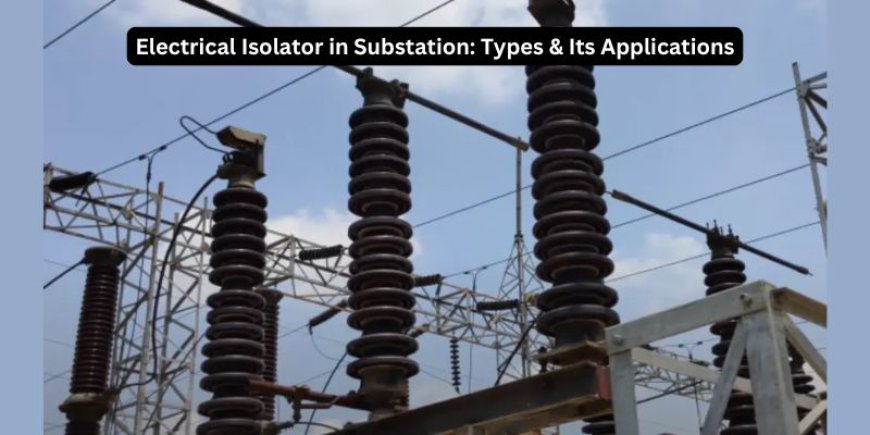
An electrical isolator in substation is a mechanical switch that helps to disconnect part of an electrical circuit when needed, usually for maintenance or safety. These switches are designed to open circuits when there is no load (current) flowing through them, meaning they should never be used while the circuit is live. Isolators are typically found at both ends of a circuit breaker, allowing workers to safely perform repairs without exposing themselves to the risk of electric shock. Understanding how isolators work is fundamental in learning about electrical safety and circuit management.
Types of Electrical Isolator

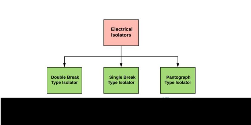
Based on the requirement, Electrical isolators are classified into three types. Here are:
-
Double Break Type Isolator
-
Single Break Type Isolator
-
Pantograph Type Isolator
Double Break Type Isolator
This isolator has three main components called post-insulators. The middle one holds a contact that can be rotated by turning the central part of the isolator. You can rotate the middle part using a lever at the bottom, which either works by hand or through a motor. The motorised version uses a motor to move the isolator, making it easier to operate compared to the manual version.
Single Break Type Isolator
In this isolator design, there are two parts to the arm contact. One part has a male connector, and the other part has a female connector. When the post insulator rotates, it moves the arm contacts into place.
The two parts of the insulator rotate in opposite directions. When they rotate in one direction, the arm contacts come together to close the isolator. When they rotate the other way, the arm contacts open, turning the isolator off. Usually, this isolator is powered by a motor, but there’s also an option for manual operation in case of an emergency.
Pantograph Type Isolator
The pantograph-type isolator is an efficient solution for current switchgear installations, requiring minimal space while maintaining functionality. It consists of a post insulator and an operating insulator, making it a practical choice for high-density installations. Depending on its placement within the power system, isolators can be categorized as bus side, line side, or transfer bus side.
-
Bus Side Isolator: This isolator is connected to the main bus, isolating it from other parts of the electrical system.
-
Line Side Isolator: It connects to the feeder on the line side, allowing isolation of the power line.
-
Transfer Bus Side Isolator: Connected to the transformer’s main bus, this isolator helps disconnect the transformer from the power system.
