L293D H-Bridge Motor Driver IC: What Is, Working, Circuits Diagram
The L293D H-Bridge Motor Driver IC is a small, powerful chip used to control the direction and speed of small DC motors.
 circuits
The L293D H-Bridge Motor Driver IC is a small, powerful chip used to control the direction and speed of small DC motors. It is especially popular in robotics and electronics projects because it can drive two motors at the same time. In this article, we will explain what L293D is, how it works, and its pin configuration.
What is L293D H-Bridge Motor Driver IC?
The L293D is a chip that allows you to control the direction and speed of two DC motors. It can handle high currents (up to 600 mA) and voltages (4.5V to 36V). This makes it suitable for use in small robots, remote-controlled cars, and other projects that involve motors.
How does L293D work?
The main function of the L293D is to control how the motor turns - whether it rotates forward or backward. It does this using a circuit called an H-bridge. The H-Bridge allows you to send current through the motor in either direction.
The L293D H-Bridge Motor Driver IC has two H-bridges, which means it can control two motors independently. Each H-bridge consists of four switches (called transistors). By opening and closing these switches in different ways, you can change the direction of current flowing through the motor. This allows you to control whether the motor rotates clockwise or counterclockwise.
Working Principle
The L293D motor driver works based on a few basic principles that govern how it controls motors. Understanding these working principles can also provide insight into the broader context of PCB types and their working principles.
- Enable Pin (EN1/EN2): This pin turns the H-Bridge on and off. If the pin is high (connected to power), the H-bridge is on. If it is low (connected to the ground), the H-bridge is closed.
- Input Pins (IN1, IN2, IN3, IN4): These pins control the direction of flow. For example, if IN1 is high and IN2 is low, the motor will spin in one direction. If IN1 is low and IN2 is high, it will spin in the other direction.
- Output Pins (OUT1, OUT2, OUT3, OUT4): These pins connect to the motor. OUT1 and OUT2 are for the first motor, while OUT3 and OUT4 are for the second motor.
- Power supply pins (Vcc1, Vcc2, GND): Vcc1 is for logic voltage (typically 5V), Vcc2 is for motor voltage (up to 36V) and GND is ground.
By controlling the input and enabling the pin, you can turn the motor forward, backward, or off. You can also control the speed of the motor using pulse width modulation (PWM) on the enable pin.
Pin Diagram and Configuration
Here's a handy guide to the pins on the L293D, which comes in a 16-pin package:
+---+---+---+
EN1 1 | +--+ 16| Vcc2
IN1 2 | | Out1
IN2 3 | | Out2
Vss 4 | | GND
GND 5 | | GND
OUT3 6 | | Out4
OUT4 7 | | Out3
Vcc1 8 | | EN2
+---+---+---+
Here's what each pin does:
- EN1 (Pin 1): Turns on/off the first H-Bridge. High = on.
- IN1 (pin 2): Input for the first H-bridge. Controls OUT1.
- IN2 (pin 3): Input for the first H-bridge. Controls OUT2.
- Vss (pin 4): logic voltage supply (typically 5V).
- GND (pins 5 and 12): Ground.
- Out1 (Pin 6): Output for the first H-Bridge.
- Out2 (pin 7): Output for the first H-bridge.
- Vcc1 (pin 8): logic voltage supply.
- Vcc2 (Pin 16): Motor voltage supply.
- Out3 (pin 15): Output for second H-bridge.
- Out4 (pin 14): Output for second H-bridge.
- IN3 (pin 10): Input for second H-bridge. Controls OUT3.
- IN4 (pin 11): Input for second H-bridge. Controls OUT4.
- EN2 (Pin 9): Turns on/off the second H-bridge. High = on.
Applications of L293D
The L293D motor driver is a simple component used in many projects. It controls motors in small robots, making them move. In automated systems, it helps manage motor functions. It is also used in remote control (RC) cars to control their motors, making them easier to maneuver. In industrial settings, the L293D drives motors in equipment, ensuring that they function well. Hobbyists like to use it in DIY projects for various motor control tasks. Additionally, knowing the types of power converters and their applications is important because the L293D often works with different converters to match voltage levels and ensure that everything works together smoothly. Here are some common examples:
- Robotics: Controls motors in small robots.
- Automation: Used in automated systems to control motors.
- RC Car: Remote control controls the car's motors.
- Industrial systems: drives motors in industrial equipment.
- DIY Projects: Popular among hobbyists for various motor control projects.
Practical implementation
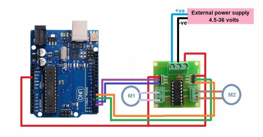
Here's a simple example of how you can use the L293D to control a DC motor with an Arduino:
Required Components:
- L293D IC
- Arduino Uno
- DC motor
- power supply
- Breadboard and jumper wire
Attachments:
- Connect EN1 to the PWM pin on the Arduino (eg, pin 9).
- Connect IN1 and IN2 to the digital pins on the Arduino (eg, pins 2 and 3).
- Connect OUT1 and OUT2 to the motor terminals.
- Connect Vss to 5V from Arduino.
- Connect GND to the ground on the Arduino.
- Connect Vcc2 to the motor power supply.
- Connect the GND pin to common ground.
Arduino Code:
int EN1 = 9;
int IN1 = 2;
int IN2 = 3;
void setup() {
pinMode(EN1, output);
PinMode(IN1, OUTPUT);
pinMode(IN2, OUTPUT);
}
void loop() {
// Forward direction
digitalWrite(IN1, HIGH);
digitalWrite(IN2, LOW);
analogWrite(EN1, 255); // Speeding up
Delay(2000);
// closed
analogWrite(EN1, 0);
delay(1000);
// reverse direction
digitalWrite(IN1, LOW);
digitalWrite(IN2, HIGH);
analogWrite(EN1, 255); // Speeding up
Delay(2000);
// closed
analogWrite(EN1, 0);
delay(1000);
}
This code moves the motor forward for 2 seconds, stops for 1 second, reverses for 2 seconds, and stops for 1 second. It repeats this cycle continuously.
Conclusion
The L293D H-Bridge Motor Driver IC is an excellent tool for controlling the direction and speed of DC motors. It is easy to use and can handle two motors simultaneously. Whether you're working on a small robot, an automated system, or any other project that involves motors, the L293D is a reliable choice. Understanding how it works and how to connect it will help you get the most out of this versatile IC.