

3D Printing Australia: Preparing CAD Designs for Reliable 3D Printing in Brisbane
Brisbane businesses developing customised products, industrial components, architectural models, and engineering accessories increasingly need manufacturing processes that can accommodate complex designs. Additive manufacturing provides an opportunity to produce physical parts directly from digital models, but the quality of the finished component depends significantly on how the design is prepared.

Introduction
Brisbane businesses developing customised products, industrial components, architectural models, and engineering accessories increasingly need manufacturing processes that can accommodate complex designs. Additive manufacturing provides an opportunity to produce physical parts directly from digital models, but the quality of the finished component depends significantly on how the design is prepared.
A component that looks correct in computer-aided design software may still present manufacturing challenges. Thin walls, insufficient clearances, unsupported features, incorrect dimensions, and unsuitable material choices can affect print quality, durability, and assembly performance.
For businesses using 3D printing services in Brisbane, preparing a design correctly can reduce unnecessary revisions and help ensure that the manufactured component meets its intended purpose.
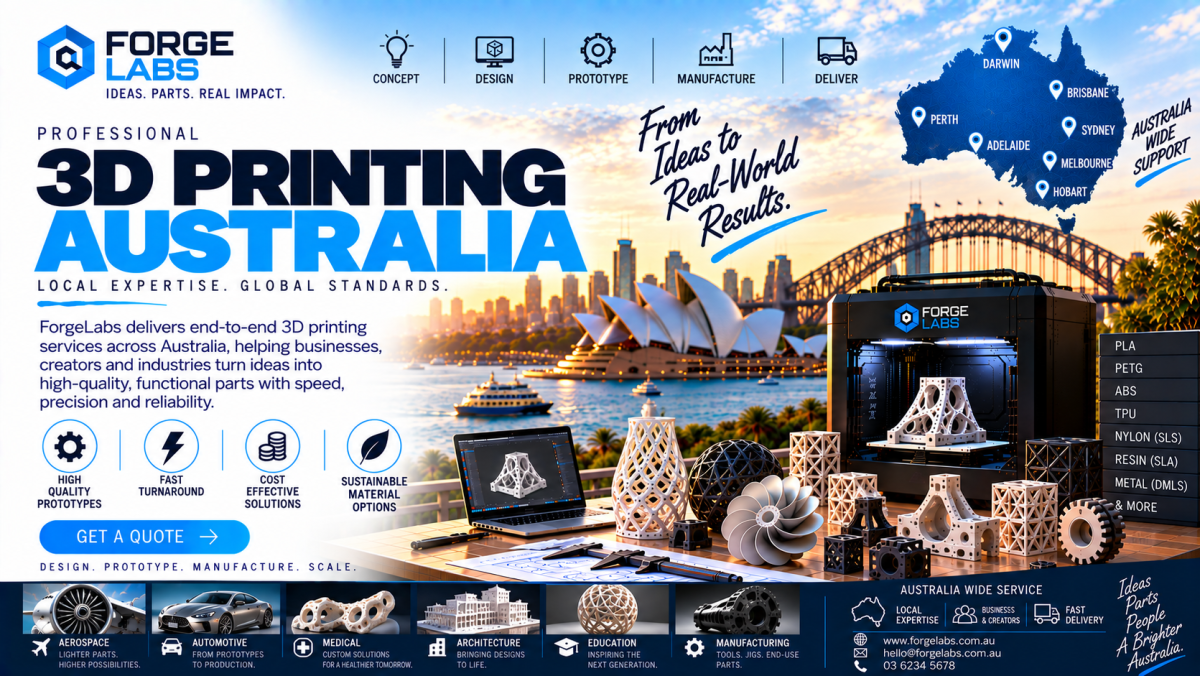
With 3D printing Australia, engineers, designers, and product developers can explore manufacturing approaches that connect digital design with practical component production. Forge Labs can support Australian businesses investigating additive manufacturing for customised components, prototypes, and suitable engineering applications.
Why CAD Preparation Matters
Computer-aided design software allows engineers to develop precise digital representations of physical components. However, a CAD model must also be suitable for the manufacturing process selected.
Additive manufacturing builds parts layer by layer, and different technologies impose different requirements on geometry, wall thickness, support structures, surface quality, and dimensional accuracy.
A well-prepared design considers these factors before production begins.
Important considerations include:
-
Overall component dimensions
-
Wall thickness and structural features
-
Openings, holes, and clearances
-
Overhangs and unsupported geometry
-
Material properties
-
Surface-finish requirements
-
Assembly interfaces
-
Post-processing requirements
Reviewing these elements early can help prevent avoidable production problems.
Selecting the Right CAD File Format
A three-dimensional design must be transferred into a format supported by the selected manufacturing workflow.
Different formats preserve different types of information.
An STL file represents the external geometry of a model using a triangular mesh. It is widely associated with 3D printing, but it does not inherently preserve the complete parametric design history or standard material information.
A 3MF file can contain additional information compared with a basic STL file, depending on the software and workflow used.
STEP files are commonly used to exchange solid CAD geometry between engineering applications. They can be useful when a design requires further engineering review or modification before manufacturing.
The best format depends on the service provider's workflow and the information needed to manufacture the component.
Before submitting a design, businesses should confirm that the selected file format preserves the geometry accurately and can be processed correctly.
Checking Model Integrity Before Production
An apparently complete CAD model may contain errors that become visible only during manufacturing preparation.
Examples include gaps in a surface, overlapping geometry, inverted mesh normals, and internal features that create an invalid solid.
These issues can prevent software from interpreting the intended component correctly.
Before sending a design for production, engineers should check that the model forms a valid, manufacturable shape.
Useful checks include confirming that surfaces are closed where required, inspecting intersecting bodies, and reviewing the model for unintended openings.
Automated repair tools can resolve some mesh problems, but repaired geometry should still be inspected to ensure that important features have not changed.
A clean digital model provides a more dependable starting point for manufacturing.
Designing Appropriate Wall Thicknesses
Wall thickness influences the strength, weight, manufacturability, and durability of a printed component.
Very thin walls may be difficult to reproduce consistently, while unnecessarily thick sections can increase material consumption and printing time.
The appropriate thickness depends on the manufacturing technology, selected material, component size, geometry, and intended loading.
For example, a decorative enclosure may have different requirements from a bracket that experiences repeated handling.
Designers should avoid applying one universal wall-thickness rule to every component.
Instead, they should consider the material's properties and the purpose of the part, then confirm that the chosen dimensions are compatible with the proposed manufacturing process.
For functional components, physical testing may be necessary to establish whether the design performs as intended.
Understanding Overhangs and Support Structures
Some geometries extend outward without sufficient material beneath them.
Depending on the printing technology, these overhangs may require temporary support structures or a different component orientation.
Supports can improve the ability to manufacture complex shapes, but they may increase production time, material consumption, and post-processing requirements.
They can also leave marks on surfaces where the supports contact the component.
Designers can sometimes reduce these challenges by modifying the geometry, changing the orientation, or dividing the component into multiple sections.
For a component with an internal cavity, for instance, the orientation may influence whether supports are necessary and whether they can be removed afterward.
The appropriate strategy depends on the selected process and the features that matter most to the finished part.
Choosing the Right Build Orientation
The orientation of a component during printing can influence several aspects of the final result.
These include surface finish, support requirements, production time, dimensional consistency, and mechanical performance.
In some layer-based processes, the direction of the layers can also affect the strength of a component under particular loading conditions.
A bracket subjected to bending may therefore require a different orientation from a decorative model with similar external dimensions.
Designers should identify the direction and type of forces that the component is expected to experience before choosing an orientation.
The orientation should also account for critical mating surfaces and visible areas where surface quality is important.
For complex components, the most practical orientation may require balancing multiple objectives rather than optimising a single feature.
Designing Holes, Slots, and Clearances
Holes and mating features are frequently used to connect printed parts to existing equipment or other components.
However, a digital dimension does not always translate into an identical physical dimension after manufacturing.
The result depends on the printing process, material behaviour, geometry, machine configuration, and finishing methods.
Small holes may reproduce differently from large openings, while internal corners and narrow slots can introduce additional challenges.
Designers should identify dimensions that are critical to assembly and communicate them clearly when requesting manufacturing.
Where a close fit is required, a suitable allowance may need to be included in the design or achieved through an appropriate finishing operation.
Test coupons or prototype parts can help establish a reliable approach before producing a larger batch.
Accounting for Material Behaviour
Different printing materials behave differently during production and use.
Some materials offer greater stiffness, while others provide flexibility or impact resistance. Certain materials are better suited to elevated temperatures or particular chemical environments.
Material behaviour can also influence dimensional changes during manufacturing and cooling.
A design that performs well in one material may require modifications when produced using another.
Before finalising a model, engineers should consider the operating environment, expected loading, temperature, moisture exposure, chemical contact, and required service life.
For example, an external equipment cover may need to withstand environmental exposure, whereas an inspection fixture may prioritise dimensional stability and repeatable positioning.
Material selection should follow the intended function rather than visual appearance alone.
Reducing Unnecessary Design Complexity
Complex geometry can be useful when it provides a meaningful functional benefit, but unnecessary features may increase manufacturing effort.
Small decorative details, difficult-to-remove supports, inaccessible internal passages, and overly complicated assemblies can make a component harder to produce or inspect.
Designers should evaluate whether each feature contributes to the component's intended performance.
Simplifying unnecessary geometry can improve manufacturability without reducing the value of the design.
For example, a mounting component may achieve the required function using carefully positioned ribs and supports instead of a completely solid internal structure.
Any change should preserve the required mechanical properties and critical dimensions.
The goal is to produce a design that balances functionality, manufacturing practicality, and overall cost.
Incorporating Assembly Requirements
Many printed components are designed to work alongside existing parts.
Examples include brackets attached to machinery, covers fitted around electrical housings, fixtures used during manufacturing, and accessories that connect to commercially available hardware.
These applications require careful consideration of interfaces.
Designers should confirm hole positions, mating surfaces, available clearances, fastener access, and the expected assembly sequence.
Where several components fit together, the relationship between their dimensions should be evaluated as a complete system.
A small dimensional error in one component may create a larger assembly problem when combined with other parts.
Producing a prototype of the interface can help identify these issues before manufacturing multiple components.
Designing for Post-Processing
Some printed parts require finishing after manufacture.
Depending on the process and material, this may include support removal, sanding, surface treatment, machining, or other finishing operations.
The design should allow these activities to be performed without damaging important features.
For example, a narrow recess may be difficult to sand, while an enclosed passage may be inaccessible for inspection.
Critical surfaces can be identified in the design brief so the manufacturing workflow can account for the required finish.
Post-processing should be considered during the design stage rather than after the component has already been manufactured.
This helps ensure that the final geometry, appearance, and performance meet the original requirements.
Preparing Designs for Functional Testing
A prototype intended for physical testing should be designed according to the questions the test needs to answer.
If the purpose is to check appearance, an economical material and straightforward geometry may be sufficient.
If the component needs to demonstrate movement, fit, or resistance to repeated handling, its material and structural features become more important.
Engineers should distinguish between visual models and prototypes intended to evaluate functional performance.
A printed component should not automatically be treated as a production-ready part simply because it fits correctly.
Depending on the application, testing may need to evaluate strength, deformation, wear, temperature resistance, or long-term performance.
Safety-critical components require appropriate engineering assessment and validation before operational use.
Preparing Files for 3D Printing Services in Brisbane
Businesses seeking manufacturing support should provide enough information for the provider to assess the design and identify potential constraints.
A CAD file is useful, but the intended application is equally important.
The information supplied should explain what the component does, how it will be used, and which dimensions or performance characteristics are particularly important.
A practical submission can include:
-
The three-dimensional model
-
Relevant engineering drawings
-
Required quantity
-
Intended application
-
Preferred material, if established
-
Critical dimensions and tolerances
-
Surface-finish expectations
-
Expected operating conditions
If a particular feature must fit an existing component, providing measurements or reference geometry can improve the assessment.
Clear information makes it easier to determine whether the design needs modification before manufacturing.
Cost Considerations During Design
Design decisions can influence manufacturing cost even before the material is selected.
Large solid components may consume more material than necessary. Complex geometries can require additional supports or finishing. Tight tolerances may require more careful production planning and inspection.
The number of parts and the need for assembly can also affect the overall project cost.
Designers should therefore evaluate the complete manufacturing requirement rather than focus exclusively on the initial printing price.
A slightly modified geometry may reduce unnecessary material, simplify support removal, or make the component easier to inspect.
However, cost-saving changes must preserve the intended function and should not compromise durability or safety.
For repeat orders, the ability to reuse a well-prepared digital model can also simplify subsequent manufacturing.
Common CAD Preparation Mistakes
Several avoidable issues can make additive manufacturing more difficult.
One common problem is supplying a model without defining important dimensions or tolerances. The component may print successfully but fail to fit an existing assembly.
Another issue is selecting material based solely on appearance instead of evaluating the operating environment.
Designers can also overlook support removal, finishing access, and the possibility that a component's orientation will affect its mechanical performance.
Insufficient testing is another concern, particularly when a prototype is intended for functional use.
These problems can often be reduced by reviewing the model before manufacturing and clearly communicating the component's intended application.
Forge Labs and Digital Design Preparation
Forge Labs can support Australian businesses exploring additive manufacturing for customised components, prototypes, and suitable engineering applications.
For companies preparing designs for manufacturing, the key considerations include file integrity, geometry, material selection, dimensional requirements, and the component's intended function.
A well-prepared CAD model provides a stronger starting point for evaluating manufacturing options.
Businesses should confirm the available materials, manufacturing capabilities, tolerances, and finishing options relevant to their project before finalising the design.
The most suitable production approach depends on the component's geometry, expected performance, quantity, and overall engineering requirements.
The Future of CAD-Driven Manufacturing
Digital design and additive manufacturing allow engineering teams to connect product development more directly with physical production.
A revised CAD model can be used to manufacture another version of a component, enabling teams to investigate design changes without recreating the entire production process.
As businesses develop more structured digital workflows, design files can also support documentation, inspection planning, and future replacement production.
For Brisbane businesses exploring specialised manufacturing requirements, effective CAD preparation can help make additive manufacturing more predictable and practical.
The greatest value comes from combining digital design flexibility with appropriate material selection, manufacturing knowledge, and physical verification.
Conclusion
Preparing a digital model correctly is an important step towards producing a reliable printed component. Geometry, wall thickness, build orientation, material properties, assembly requirements, and post-processing all influence the final result.
With 3D printing Australia, Brisbane businesses can explore customised manufacturing solutions for prototypes, engineering components, fixtures, and specialised products.
Careful CAD preparation helps reduce avoidable errors, improve the evaluation of manufacturing options, and create components that better match their intended purpose.
Forge Labs can support businesses exploring additive manufacturing by helping connect digital designs with appropriate production requirements.
Frequently Asked Questions
What should I check before submitting a CAD model for 3D printing?
Check model integrity, dimensions, wall thickness, openings, clearances, support requirements, material suitability, and critical assembly interfaces.
Which file format should I use?
Common options include STL, 3MF, and STEP. The most appropriate format depends on the provider's workflow and whether further CAD modification is required.
Can every CAD design be printed without modification?
No. Some designs require changes to wall thickness, unsupported geometry, clearances, or other features to suit the selected manufacturing process.
Does build orientation affect the finished component?
Yes. Orientation can influence surface finish, support requirements, production time, dimensional consistency, and mechanical performance.
How can I improve the fit of a printed component?
Identify critical interfaces, establish suitable tolerances, confirm the manufacturing process, and test the fit using a prototype where necessary.
Does a successful prototype guarantee production performance?
No. Functional performance depends on the material, design, manufacturing process, and operating conditions. Additional testing may be required for demanding applications.
Can complex geometries be manufactured using additive manufacturing?
Many complex geometries can be produced, but suitability depends on feature size, support requirements, material, manufacturing technology, and post-processing access.
Can Forge Labs support customised CAD-based manufacturing projects?
Forge Labs can support additive manufacturing projects involving customised components, prototypes, engineering fixtures, and other suitable manufacturing applications.












Comments (0)